


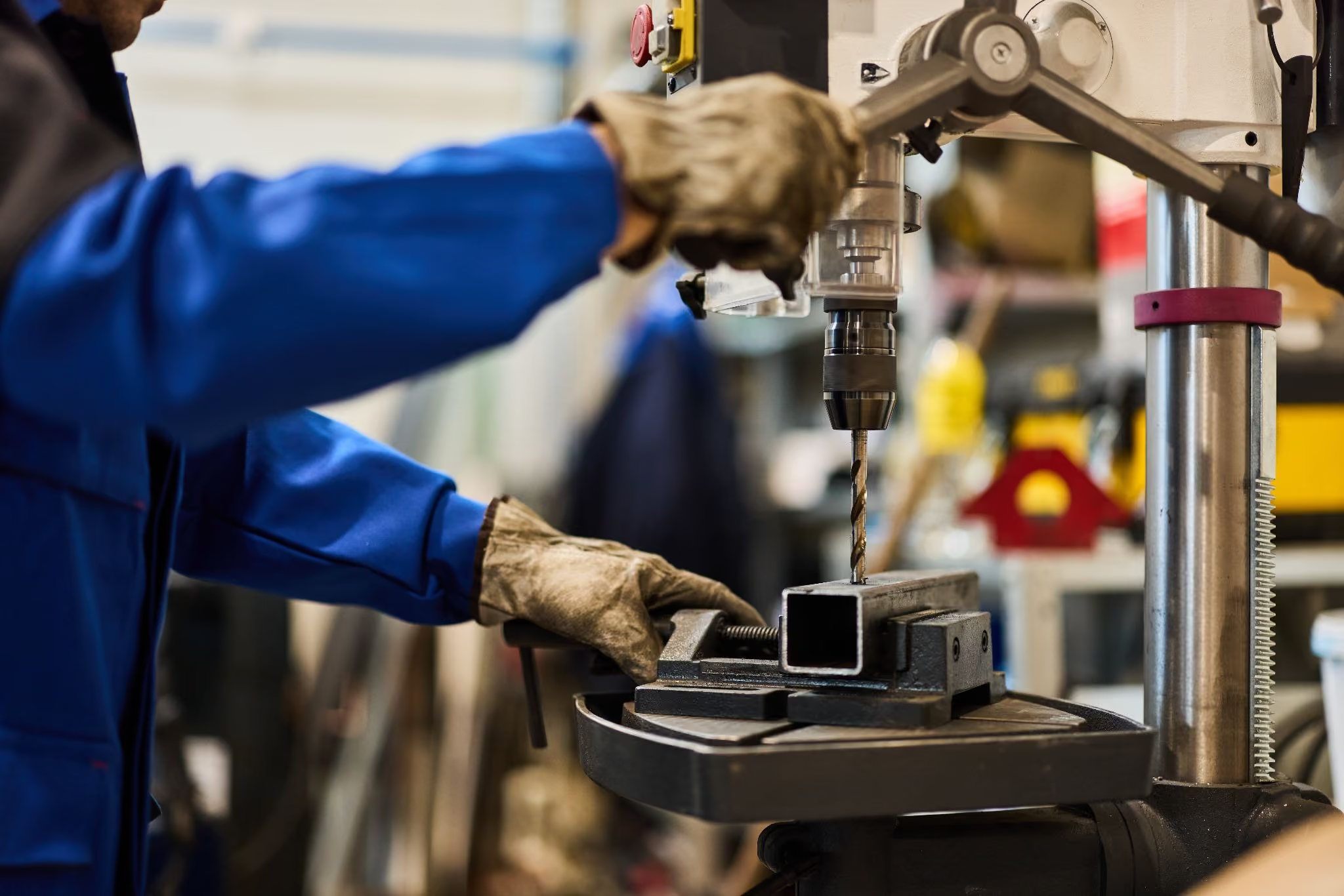
High-powered automated drilling equipment significantly increases workshop throughput but requires strict adherence to engineered mechanical limits to ensure operator safety and machinery longevity. Maintaining a safe floor relies on three core operational pillars: precisely calculating combined thrust loads to prevent catastrophic structural deflection, enforcing the absolute 4,000 RPM limit on multi-spindle gearboxes to avoid thermal bearing failure, and executing scheduled preventive maintenance such as 750-hour grease intervals and proper guide rod alignment. Selecting the right tool-holding system—such as ER collets for zero-defect production or key-type chucks within balanced speed ranges—further eliminates hazards like tool runout and component detachment.
In high-volume manufacturing environments, upgrading to automated drilling units and multi-spindle platforms is the most effective method for accelerating production cycles. However, as machinery becomes more robust and forces escalate, workshop safety must transition from basic common-sense rules to rigorous engineering protocols. High-powered machinery operates with immense torque and linear force, meaning that an overlooked mechanical limitation can quickly result in tool breakage, ruined workpieces, or severe hazards. Achieving a safe, zero-defect production floor requires a deep understanding of the mechanical forces, thermal limits of internal gearing, and structural requirements of tool holding systems. This checklist covers the critical protocols required to keep your high-powered drilling operations smooth, predictable, and completely safe.
In this guide we'll:
- Outline methods for calculating multi-spindle thrust loads to prevent equipment damage.
- Establish strict operational limits for internal helical gear assemblies to avoid thermal breakdown.
- Compare tool-holding mechanics and maintenance schedules required to ensure a stable workshop floor
Calculating combined loads and thrust limits
The most fundamental safety protocol when operating automated equipment is verifying that your machine can withstand the physical forces required for the cut. Every drill bit demands a specific downward force to penetrate material, known as the thrust load. When driving multiple spindles simultaneously, this force multiplies linearly.
To evaluate whether an application is safe for your current setup, engineers must use the standard multi-spindle thrust formula: Total thrust required = Single hole thrust × Number of spindles.
For example, drilling a single 1/2-inch hole in soft aluminum requires 180 pounds of thrust. If you are utilizing a multi-spindle head to drive four holes at once, the total thrust required becomes 720 pounds. This application is entirely safe for heavy-duty drilling units rated for higher capacities, but it would easily overwhelm lighter workshop equipment.
When materials harden, the numbers become far more extreme. Drilling a 1/2-inch hole in stainless steel requires 1,185 pounds of thrust. Multiplying that by four spindles results in a massive 4,740 pounds of combined force. Exceeding equipment limits causes rapid tool deflection, premature bearing fatigue, and potential structural failure of the machine frame or spindle. If a planned operation exceeds the maximum rating of your heaviest industrial unit—typically 1,500 pounds for a standard heavy-duty series like the 5000 Series—the application must be flagged for senior technical evaluation and custom engineering before any cycles begin.
For through-hole applications, one engineered method to mitigate extreme thrust loads is staggering the tool lengths. By adjusting individual drill bit depths, the bits break through the material at different intervals, preventing the peak force from hitting the machine simultaneously. However, this configuration requires precise engineering validation to maintain alignment and balance.
Enforcing the 4,000 RPM rule
In a busy job shop, it is often tempting to increase spindle speeds to shave seconds off a cycle time, especially when drilling small holes in ductile materials like aluminum. While single-spindle units can frequently sustain speeds up to 6,000 RPM, multi-spindle head attachments operate under a strict mechanical ceiling.
All multi-spindle heads utilize internal hardened steel helical gearing to distribute power from the main drive to individual spindles. These gears generate significant friction, stress, and heat during high-speed rotation. Because of these intense thermal dynamics, there is an absolute speed limit for multi-spindle head gearing: 4,000 RPM maximum, with no exceptions.
Exceeding the 4,000 RPM threshold causes the internal grease to break down rapidly, leading to overheating, severe gear wear, and catastrophic bearing failure. If your production process demands higher rotational speeds, do not attempt to force a multi-spindle head past its engineered limits. Instead, the correct safety protocol is to transition to a custom multiple-unit configuration, such as a dual-drive system. These setups mount separate, independent single-spindle drilling units on a shared frame driven by a single motor, allowing each unit to run safely at its maximum individual speed rating while consolidating workspace.
Tool holding security and precision selection
Selecting the correct tool holding method is a crucial factor in eliminating operational runout and preventing tool detachment hazards. Workshops generally choose between traditional key-type drill chucks and precision ER collet systems, depending on the volume and accuracy requirements of the job.
Key-type chucks offer excellent versatility for low-volume job shops experiencing frequent changeovers. They allow operators to adjust for varying tool diameters quickly using a standard key, avoiding the need to maintain an extensive collet inventory. However, three-jaw chucks inherently possess more runout potential, making them poorly suited for tight-tolerance production. Furthermore, if a key-type chuck is subjected to excessive vibration or improper torque during tightening, the drill bit can slip or detach completely during operation.
For high-volume production, integrated manufacturing cells should standardize on ER collet systems. Collets wrap completely around the circumference of the tool shank, providing superior clamping force, consistent mechanical retention, and minimal runout. Minimizing tool wobble ensures hole roundness and prevents the sudden tool binding that frequently snaps bits. Proactively measuring Total Indicated Runout on the spindle helps identify worn internal bearings or a damaged spindle shaft before a major run.
Implementing guide rod systems and advanced feed control
When multi-spindle heads feature wide spans or carry heavy tool loads, the lateral force can cause the assembly to deflect during the stroke. To combat this, precision ground guide rods with bronze bushings must be integrated to stabilize the head and maintain perfect linear alignment. The installation of these guide rod components follows strict mechanical rules to prevent binding. For standard drilling setups utilizing external guide blocks, the guide rod is locked securely to the multi-spindle head using a set screw. The bronze bushings are placed strictly at the slide points within the guide blocks, allowing the assembly to stroke smoothly without metal-on-metal galling. For unique tapping fixtures where the customer's plate or table serves as the base, the locking point shifts to the external structure, and the bronze bushings are installed directly inside the multi-spindle head itself.
In addition to physical guidance, advanced feed sequences can eliminate entry and exit hazards. For instance, when processing multi-wall structures, square tubing, or stacked sheets, traditional constant feed mechanisms waste valuable seconds cutting through empty space. Utilizing specialized multi-wall sequences—such as the advanced SkipFeed sequence exclusive to the heavy-duty 5200 Series—allows the unit to fast-traverse through empty air gaps at maximum speed, dropping back into a precise feed rate microseconds before contacting the next metal layer. This ensures clean breakthroughs, protects the tool, and minimizes structural stress on the entire system.
Preventative maintenance intervals with AutoDrill
High-powered automated machinery cannot maintain safety standards without strict preventative maintenance. Multi-spindle attachments operate under high pressure and constant friction, making routine service mandatory.
The standard reliability protocol requires multi-spindle gearboxes to be completely re-greased every 750 operating hours. Neglecting this window leads to grease crystallization, increased friction, and eventual bearing seizure. Additionally, high-volume production environments should always keep a designated repair kit on hand containing common wear items like replacement bearings and seals. Proactively replacing a worn component at the first sign of wear prevents sudden line stoppages and dangerous mechanical jams mid-cycle.
By strictly respecting thrust limits, enforcing the 4,000 RPM gearbox limit, securing tooling with precision collets, and maintaining rigid 750-hour lubrication schedules, manufacturers can completely engineer risk out of their automated drilling cells. Safety and profitability go hand in hand; a well-maintained, correctly configured machine is a secure, efficient asset that delivers flawless parts for years to come.